
17
Let's develop a QR Code Generator, part IV: placing bits
Ok, now we've finally got our error correction data, and it's time to place all those codewords into the matrix!
So, we know there are parts of the QR code that are reserved. This leaves only the light modules below as fillable with our data:

In the figure above (the size of a version 2 QR code, i.e. the one we need for our example), the brown areas are fixed pattern areas, while the dark teal modules are reserved areas for encoding information (see the next part).
Before starting, let's estabilish the way to place our modules.

Not really, dear Padme, not really…
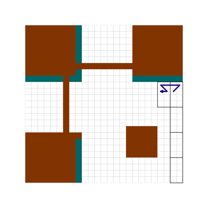
First thing, we start from the bottom right corner. Not actually a problem, here, as QR codes have the finder and alignment patterns exactly for being able to be read even when upside down.
Then we move to the left. And that's ok.
Then up and to the right. Wait, what?!
Then to the left again. And again up and to the right!

Now we've filled the first codeword. Remember that the first module corresponds to the leftmost bit of the first codeword. In our example (the string https://www.qrcode.com/), the first codeword is 65, or 01000001 in binary, so the first module will report 0, not 1, and thus it will be light; the second one will be dark, then 5 more light modules, and finally a dark module.

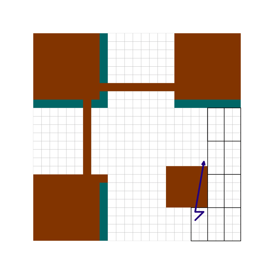
Then we proceed with thq zig-zag pattern towards the top of the grid. Once we've filled the last two columns, we can expect that we're going to fill the adjacent two columns next, with the same zig-zag movement. And that's correct, but we're starting from the top now:
And if you think we'll start the next two columns from the bottom, you guessed right. The problem here is that the alignment pattern is now in the way. The solution? Just skip it:
Moving on, we will resume the usual zig-zag pattern, until we find more reserved areas, which we're going to skip. And since the 7th column is always entirely reserved, we can pretend it doesn't even exist and we'll skip it altogether.
This is how we're going to fill a version 2 QR code:
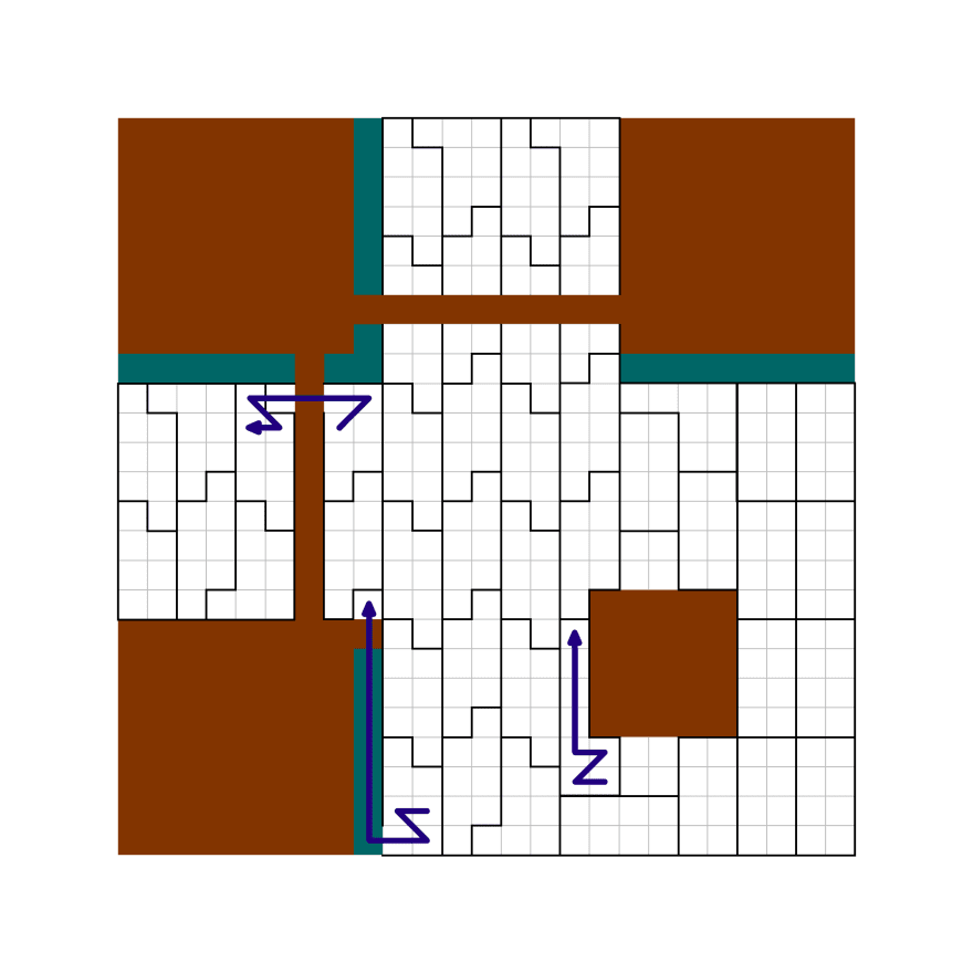
I hope the images are pretty clear on how to proceed. But just in case, we can sum everything up with the following steps (remember that every time we end up on a module that doesn't belong to a reserved area, we shall use it for data):
- start from the bottom left corner;
- move to the left;
- if we're not on the first row, move above and to the right, then go to step 2; otherwise proceed to step 4;
- if we're on the 8th column, move twice to the left; otherwise move to the left;
- move to the left;
- if we're not on the last row, move below and to the right, then go to step 5; otherwise proceed to step 7;
- if we're not on the first column, move to the left, then go to step 2; otherwise we're done 🙌
Also, notice how the last "codeword" has only 7 bits: we have no use for that, and those 7 bits are just remainder space. Versions from 2 to 6 all have 7 remainder bits, while other versions might have 0, 3 or 4 remainder bits.
It kind of feels like we've solved a maze, doesn't it? But why did we have to torture ourselves with this obscure path?
… I honestly have no idea. Really, if someone has some clues about it, please speak up 😭
At this point, after placing all the modules and the fixed patterns, we should end up with this:
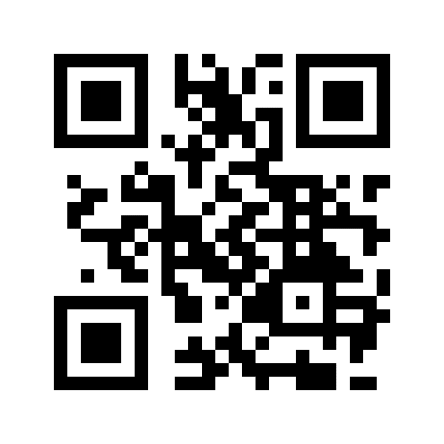
Wow, it definitely looks like a QR code! Alas, if you try to scan it, it doesn't work. Some parts are missing (the ones about error level and masking info, marked in dark teal in the figures above), and also it lacks masking. We'll get a working QR code at the end of the next part though!
I'll be clear: actually showing a QR code is just a visualization problem. We can do it with an SVG, a <canvas>, a bunch of square <span>s, or even these two emojis: ⬜⬛. It's not really important, nor difficult for someone with a minimal expertise in rendering stuff on the web.
What is important is getting the matrix of bits that will allow us to create such figure.
Let's start with actually storing the data. Again, out of convenience we can use just an array of arrays - i.e., a matrix - to record whether a module is light (0) or dark (1). But for the rows we can use Uint8Arrays again, because they're faster than regular arrays and also for the .set() method that comes in handy. We'll start simple:
function getSize(version) {
  return version * 4 + 17;
}
function getNewMatrix(version) {
  const length = getSize(version);
  return Array.from({ length }, () => new Uint8Array(length));
}
The second argument of Array.from is basically a map function that lets us using a new typed array for each row (i.e., new Array(length).fill(new Uint8Array(length)) would use the same array for each row).
Now we need a function that fills a designed area with ones or zeroes, because it'll be useful for fixed patterns:
function fillArea(matrix, row, column, width, height, fill = 1) {
  const fillRow = new Uint8Array(width).fill(fill);
  for (let index = row; index < row + height; index++) {
    // YES, this mutates the matrix. Watch out!
    matrix[index].set(fillRow, column);
  }
}
At this point, we need the sequence of modules that we need to fill with our codewords. Our strategy will be:
- start with an empty matrix;
- mark with ones the reserved areas;
- apply the 7-step iteration above - or a similar one.
function getModuleSequence(version) {
  const matrix = getNewMatrix(version);
  const size = getSize(version);

  // Finder patterns + divisors
  fillArea(matrix, 0, 0, 9, 9);
  fillArea(matrix, 0, size - 8, 8, 9);
  fillArea(matrix, size - 8, 0, 9, 8);
  // Alignment pattern - yes, we just place one. For the general
  // implementation, wait for the next parts in the series!
  fillArea(matrix, size - 9, size - 9, 5, 5);
  // Timing patterns
  fillArea(matrix, 6, 9, version * 4, 1);
  fillArea(matrix, 9, 6, 1, version * 4);
  // Dark module
  matrix[size - 8][8] = 1;

  let rowStep = -1;
  let row = size - 1;
  let column = size - 1;
  const sequence = [];
  let index = 0;
  while (column >= 0) {
    if (matrix[row][column] === 0) {
      sequence.push([row, column]);
    }
    // Checking the parity of the index of the current module
    if (index & 1) {
      row += rowStep;
      if (row === -1 || row === size) {
        rowStep = -rowStep;
        row += rowStep;
        column -= column === 7 ? 2 : 1;
      } else {
        column++;
      }
    } else {
      column--;
    }
    index++;
  }
  return sequence;
}
We did some changes in the function above. First of all, we're using rowStep to track whether we're going upwards or downwards in the matrix. Then we're using index and its parity to determine if we need to go left, or move diagonally.
For our version 2 QR code, we should end up with this:
getModuleSequence(2)
// Uint8Array(359) [[24, 24], [24, 23], [23, 24], ..., [16, 0]]
It's finally time to place our data (both message and error correction modules)!
function getRawQRCode(message) {
  // One day, we'll compute these values. But not today!
  const VERSION = 2;
  const TOTAL_CODEWORDS = 44;
  const LENGTH_BITS = 8;
  const DATA_CODEWORDS = 28;

  const codewords = new Uint8Array(TOTAL_CODEWORDS);
  codewords.set(getByteData(message, LENGTH_BITS, DATA_CODEWORDS), 0);
  codewords.set(getEDC(byteData, TOTAL_CODEWORDS), DATA_CODEWORDS);

  const size = getSize(VERSION);
  const qrCode = getNewMatrix(VERSION);
  const moduleSequence = getModuleSequence(VERSION);

  // Placing the fixed patterns
  // Finder patterns
  [[0, 0], [size - 7, 0], [0, size - 7]].forEach(([row, col]) => {
    fillArea(qrCode, row, col, 7, 7);
    fillArea(qrCode, row + 1, col + 1, 5, 5, 0);
    fillArea(qrCode, row + 2, col + 2, 3, 3);
  });
  // Separators
  fillArea(qrCode, 7, 0, 8, 1, 0);
  fillArea(qrCode, 0, 7, 1, 7, 0);
  fillArea(qrCode, size - 8, 0, 8, 1, 0);
  fillArea(qrCode, 0, size - 8, 1, 7, 0);
  fillArea(qrCode, 7, size - 8, 8, 1, 0);
  fillArea(qrCode, size - 7, 7, 1, 7, 0);
  // Alignment pattern
  fillArea(qrCode, size - 9, size - 9, 5, 5);
  fillArea(qrCode, size - 8, size - 8, 3, 3, 0);
  qrCode[size - 7][size - 7] = 1;
  // Timing patterns
  for (let pos = 8; pos < VERSION * 4 + 8; pos += 2) {
    qrCode[6][pos] = 1;
    qrCode[6][pos + 1] = 0;
    qrCode[pos][6] = 1;
    qrCode[pos + 1][6] = 0;
  }
  qrCode[6][size - 7] = 1;
  qrCode[size - 7][6] = 1;
  // Dark module
  qrCode[size - 8][8] = 1;

  // Placing message and error data
  let index = 0;
  for (const codeword of codewords) {
    // Counting down from the leftmost bit
    for (let shift = 7; shift >= 0; shift--;) {
      const bit = (codeword >> shift) & 1;
      const [row, column] = moduleSequence[index];
      index++;
      qrCode[row][column] = bit;
    }
  }
  return qrCode;
}
We'll get a version 2 proto-QR code. With "proto" I mean it hasn't been transformed by the last action: masking. It consists in XOR'ing all the modules with one of 8 predefined patterns. And why should we do that, you might ask?
Well, this time it does make sense. If you have a look at our proto-QR code, there are large areas uniformly filled with dark or light patterns, and scanners generally don't like them as they might mismatch the grid or miscount the rows or columns. So we'll have to apply a mask in order to minimize this problem.

We'll see how to do this in the next part of the series! 👋
17