41
WebGL 3D Engine From Scratch Part 6: Procedural Sphere Generation
As I was writing the next edition of this series on lighting I found that the shapes that we're dealing with are inadequate to really show off what we're trying to achieve. To do so we really need curved shapes where normal interpolation matters. The simplest of these shapes is of course the sphere. As you might expect a sphere doesn't translate easily into triangles, how it looks is very dependent on how many vertices you actually have. Due to this it doesn't make sense to have hardcoded sphere data, we need to generate the shape based on some parameters.
As it turns out there's not just one type of sphere, there are actually many ways to do this. These might include:
Since I wasn't planning a large post about spheres (lol) I'm just going to deal with the first because it's the easiest.
Positions aren't too bad to generate especially now that we have the
latLngToCartesian function. What we'll do is iterate over latitude and longitude kinda like how we would over X and Y to draw a square.export function sphere(density){
const radsPerUnit = Math.PI / density;
const sliceVertCount = density * 2;
const positions = [];
let latitude = -Math.PI / 2;
//latitude
for(let i = 0; i <= density; i++){
if(i === 0 || i === density){ //polar caps
positions.push(latLngToCartesian([1, latitude, 0]));
} else {
let longitude = 0;
for (let j = 0; j < sliceVertCount; j++) {
positions.push(latLngToCartesian([1, latitude, longitude]));
longitude += radsPerUnit;
}
}
latitude += radsPerUnit;
}
...First, I'm using a density parameter. This is not a great name but it basically describes the density of the vertices, that is each unit of density adds another band of vertices to the sphere. A density less than 2 is degenerate and will not make a useful shape. There are special cases at the polar caps. We can just add the point. For each "band" of vertices we generate a ring by moving around the longitude. This uses
density * 2 because it has to rotate 2*PI instead of PI like latitude does. This allows use to control the sphere with one number though we can just as easily split it into 2 if necessary.Nothing interesting here:
//colors
const colors = [];
for(let i = 0; i < positions.length; i++){
    colors.push([1, 0, 0]);
}So we have a cloud of points, here's where it gets tricky. We need to have an algorithm that properly makes the triangles and does so with the correct winding order.
//triangles
const triangles = [];
for(let ring = 0; ring < density - 1; ring++){ // start at first ring
    const initialP = (ring * sliceVertCount) + 1;
    for (let sliceVert = 0; sliceVert < sliceVertCount; sliceVert++){
        const thisP = initialP + sliceVert;
        const nextP = initialP + ((sliceVert + 1) % sliceVertCount);
        if(ring === 0){
            triangles.push([0, nextP, thisP]);
        }
        if(ring === density - 2){
            triangles.push([thisP, nextP, positions.length - 1])
        }
        if(ring < density - 2 && density > 2){
            triangles.push([thisP, nextP + sliceVertCount, thisP + sliceVertCount])
            triangles.push([thisP, nextP, nextP + sliceVertCount])
        }
    }
}
Starting at the bottom (minimum y) of the shape we work our way up. Since the starting and ending point are always fixed we'll start on the first real "ring" which will be ring 0. This means that the last ring of positions is row
density - 2. This can be a little confusing but if you get it wrong just play with the start and ending indices until it works.For each ring we'll iterate to each vertex, the total of which is
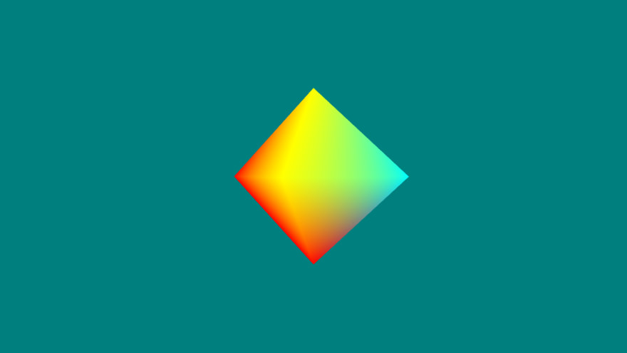
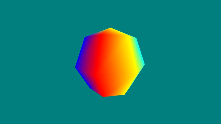
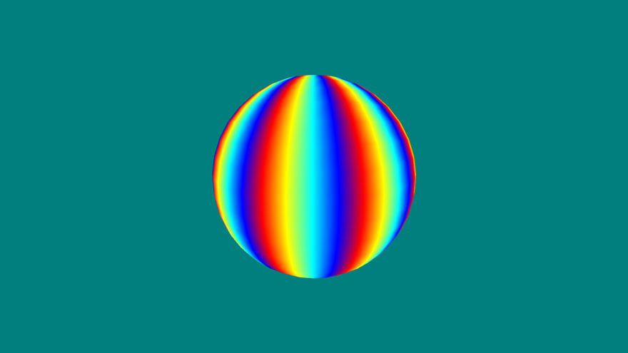
sliceVertCount from above. The current vertex is thisP. We also find what the next vertex in the ring would be nextP and this will wrap around once we hit the end of the ring. Now there are 3 cases. For ring 0, each vertex is part of the bottom pyramid so we make a triangle with the bottom point and the next point. For ring density - 2, the vertex is part of the top pyramid and so we make that triangle with the top point and the next point. If the ring index is greater than 0 and density is greater than 2, that means the sphere has quad bands and so we construct the quad with the ring above. The corresponding vertex in the next band will be sliceVertCount vertices ahead. And so with the four vertices thisP, nextP, thisP + sliceVertCount, and nextP + sliceVertCount we have a quad and so we add both triangles of the quad. The real trick here is to make sure the winding order is correct. For our engine this means counter-clockwise and by convention I like to start in the lower left.Let's Look at the results (for this I accidentally used 4 element colors in the color loop even though the attribute expects 3 element values but it actually made it easier to visualize than a solid color so I kept it):
Density 2:
Density 3:

Density 4:
Density 20:
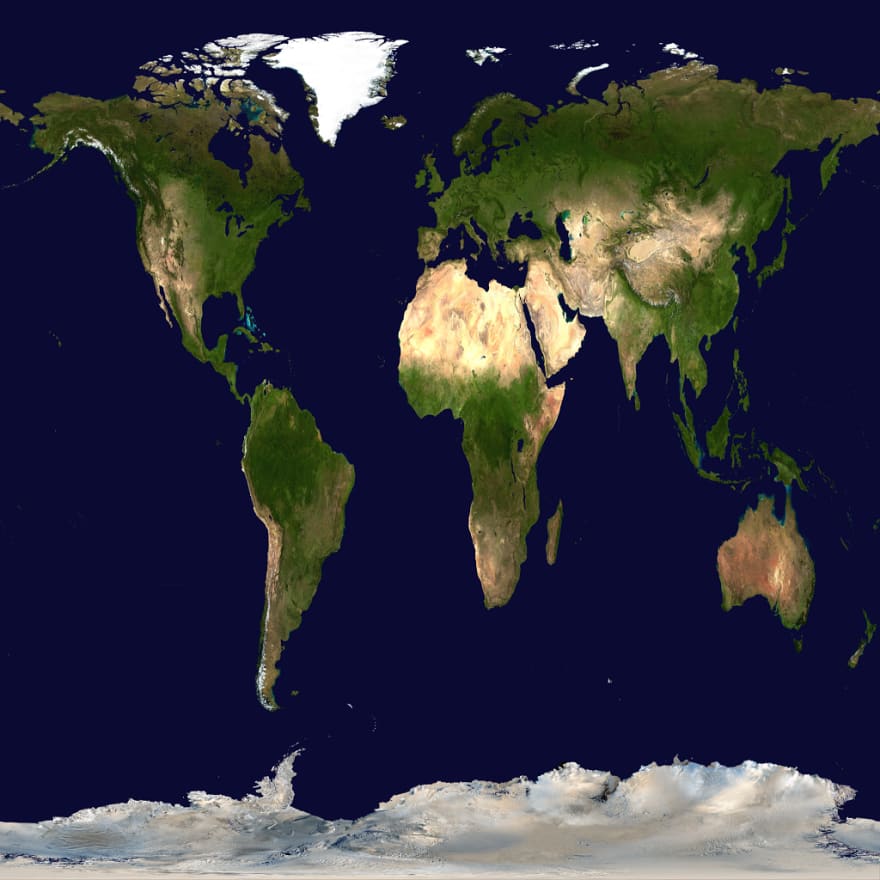
It's called a UV sphere because it's easier to think about the UVs. You can design textures in an equirectangular format, think the normal classroom world map poster where the latitude and longitude are spread out like a grid. One downside is that the triangles will all be different sizes so you'll get more stretching.
Since we're really just mapping with lat/long it makes sense to build the UVs when we still have access to that information, so we'll use the same loop where we build the positions:
//positions and UVs
const positions = [];
const uvs = [];
let latitude = -Math.PI / 2;
//latitude
for(let i = 0; i <= density; i++){
    if(i === 0 || i === density){ //polar caps
        positions.push(latLngToCartesian([1, latitude, 0]));
        uvs.push(0.5, latitude > 0 ? 1 : 0);
    } else {
        let longitude = 0;
        //longutude
        for (let j = 0; j < sliceVertCount; j++) {
            positions.push(latLngToCartesian([1, latitude, longitude]));
            uvs.push([inverseLerp(0, TWO_PI, longitude), inverseLerp(-QUARTER_TURN, QUARTER_TURN, -latitude)])
            longitude += radsPerUnit;
        }
    }
    latitude += radsPerUnit;
}
There's only 3 new lines here: declaring the UV array, pushing the end points, and pushing the UV of any other point. The endpoints don't really have an X component so we'll just say it's
0.5, we also don't need to calculate anything because it's either PI / 2 or -PI / 2 so we can just immediately set it as 0 or 1 in the V coordinate based on if it's negative or not. For all other points we do 2 inverse lerps one for U and one for V. An "inverse lerp" if you're unfamiliar takes a value in a range and converts it to a normalized value between 0 and 1. The range for U is 0 to 2*PI and the range for V is -PI/2 to PI/2.Here's what
inverseLerp looks like:export function inverseLerp(start, end, value) {
return (value - start) / (end - start);
}Since the values that come back are between 0 and 1 we don't need any further modification, they are already in the correct format for UVs. It is worth pointing out that you need the negative latitude though because UVs grow in the direction of the pixels (ie top-down).
To construct a texture to map I took this equirectangular projection of Earth from wikipedia scaled it down and then squished it from a rectangle to a square (because square textures are easier to deal with).
Then we just hook it up to our texture loader and associate with the sphere using the texture name.
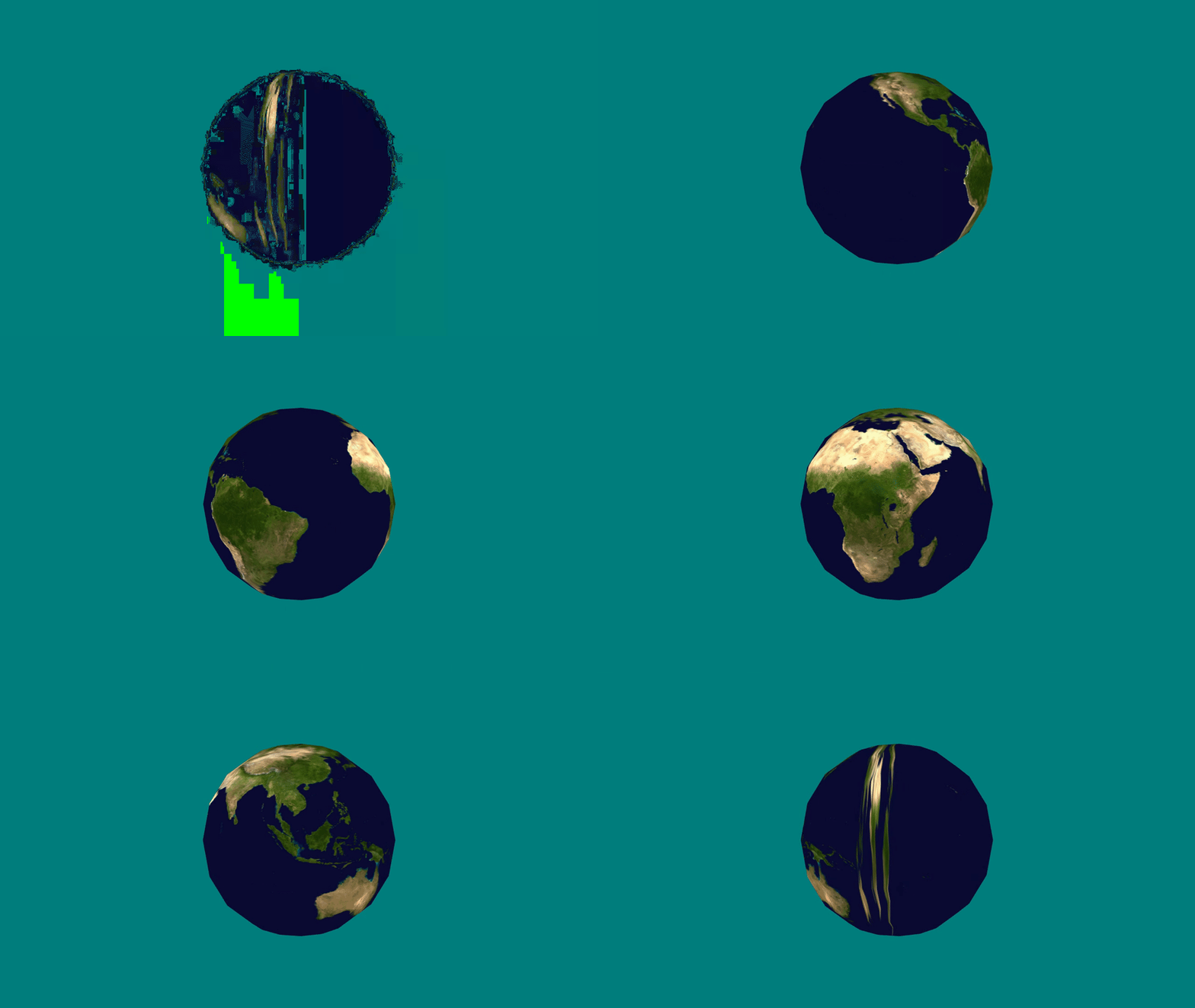
Ignore the green flash, that's just some encoding error with FFMPEG I couldn't get rid of but it looks like there's a weird seam on the sphere where Oceana is. This is due to how the UVs are generated. Normally they are increasing as we move right but at the very last set we go from a high value to a low one, like
0.95 to 0 (these are not the exact values though). This causes the UV plotting to go haywire because we're now trying to map from 0 to 0.95 going left instead of right and we get a seam. Sadly this is actually a problem with the vertices, we need the ones on the seam to be both 0 and 1 which is not possible because only 1 set of UVs can be associated with a vertex. So we actually need to change our code to duplicate the final vertex of each ring so that we can have a different UV value, sucks but 'dems the rules.//positions and UVs
const positions = [];
const uvs = [];
let latitude = -Math.PI / 2;
//latitude
for(let i = 0; i <= density; i++){
const v = inverseLerp(-QUARTER_TURN, QUARTER_TURN, -latitude);
if(i === 0 || i === density){ //polar caps
positions.push(latLngToCartesian([1, latitude, 0]));
uvs.push(0.5, latitude > 0 ? 0 : 1);
} else {
let longitude = 0;
//longitude
for (let j = 0; j < sliceVertCount; j++) {
positions.push(latLngToCartesian([1, latitude, longitude]));
uvs.push([inverseLerp(0, TWO_PI, longitude), v]);
if (j === sliceVertCount - 1) { //on the last set we create a seperate vertex for the UV end
positions.push(latLngToCartesian([1, latitude, longitude + radsPerUnit]));
uvs.push([1, v]);
}
longitude += radsPerUnit;
}
}
latitude += radsPerUnit;
}Not too bad, we need to add a final overlapping vertex at the end of each ring. I've also stopped recalculating the V per loop since it's the same.
Triangle generation isn't too bad either.
//triangles
const triangles = [];
for(let ring = 0; ring < density - 1; ring++){ // start at first ring
    const initialP = (ring * (sliceVertCount + 1)) + 1;
    for (let sliceVert = 0; sliceVert < sliceVertCount; sliceVert++){
        const thisP = initialP + sliceVert;
        const nextP = initialP + sliceVert + 1;
        if(ring === 0){
            triangles.push([0, nextP, thisP]);
        }
        if(ring === density - 2){
            triangles.push([thisP, nextP, positions.length - 1])
        }
        if(ring < density - 2 && density > 2){
            triangles.push([thisP, nextP + sliceVertCount + 1, thisP + sliceVertCount +1])
            triangles.push([thisP, nextP, nextP + sliceVertCount + 1])
        }
    }
}
Instead of taking the modulus to wrap back around we can simply remove it. Also
initialP needs to take into account that there is an extra vertex per row.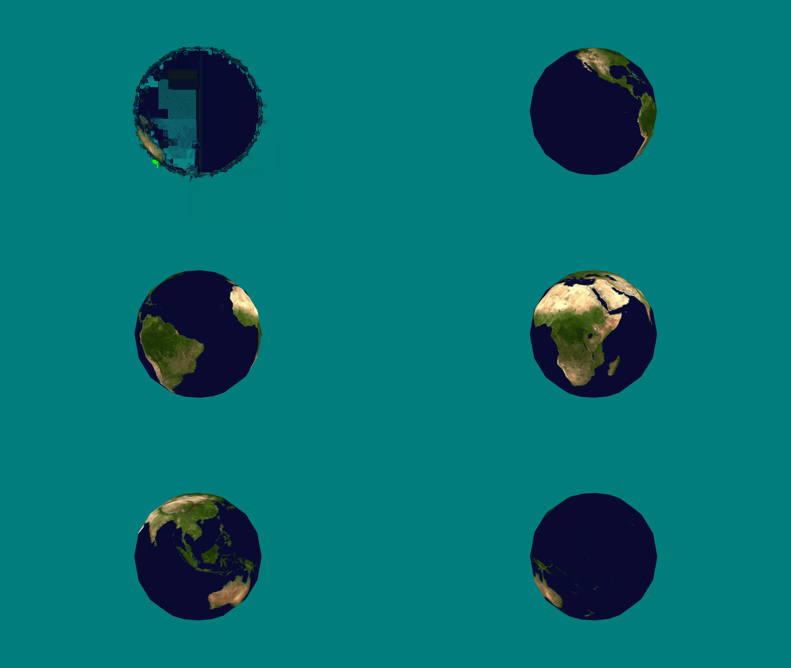
Looking good. ...Wait what's going on at the poles?
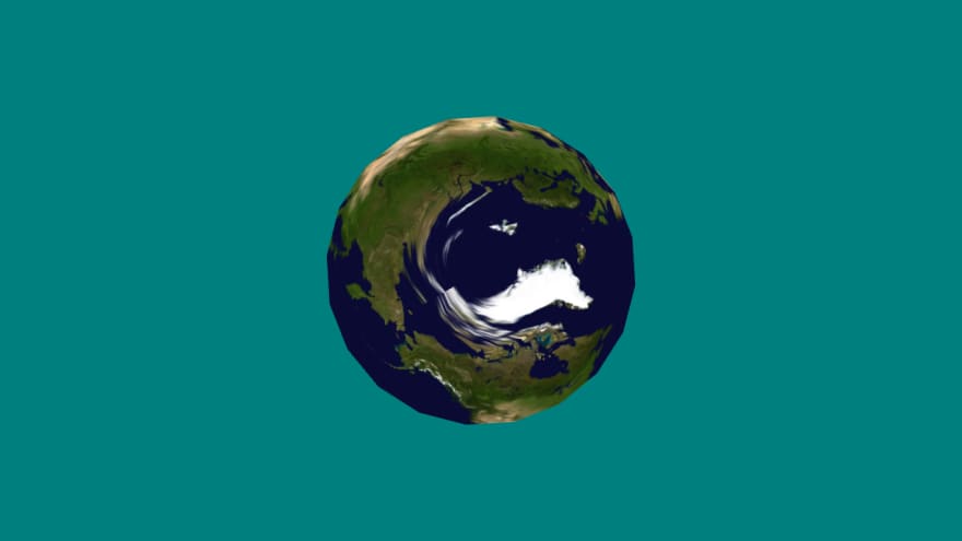

So it turns out we have the exact same problem at the poles but a bit less obvious why. We picked
0.5 as the U value at the poles because it really shouldn't matter what the point is because the first and last rows are complete compressed horizontally into a single point....Except it does. Consider a meridian (vertical line) running down the sphere, in texture space it should always have the same U value. The problem is that we neglected that we need to interpolate to that point! So even though the final U value is irrelevant, the values between the pole and the top and bottom rings do matter and if the final U has a horizontal offset it will create a swirl effect across those triangles as it moves horizontally.
So to fix it we need multiple overlapping vertices at the poles, each with a different U value so that the rings line up correctly.
The way we'll do this is to represent the pole not as a single point but as a ring of points just like the other rings except with a radius of 0.
//positions and UVs
const positions = [];
const uvs = [];
let latitude = -Math.PI / 2;
//latitude
for(let i = 0; i <= density; i++){
    const v = inverseLerp(-QUARTER_TURN, QUARTER_TURN, -latitude);
    let longitude = 0;
    let vertLength = sliceVertCount + ((i > 0 && i < density) ? 1 : 0); //middle rings need extra vert for end U value
    //longitude
    for (let j = 0; j < vertLength; j++) {
        positions.push(latLngToCartesian([1, latitude, longitude]));
        uvs.push([inverseLerp(0, TWO_PI, longitude), v]);
        longitude += radsPerUnit;
    }
    latitude += radsPerUnit;
}
Things just got simpler. We no longer need special cases for the first and last point inside the loop. However, as it turns out the poles do not need an extra vertex to deal with the U coordinate wrapping so we still wind up special casing it so we don't get unused vertices.
Generating triangles again takes a little more thought (seriously if you find it hard to figure out all the off-by-one errors a pencil and paper is your best friend, step-through with the debugger and draw it out!).
//triangles
const triangles = [];
let ringStartP = 0;
for(let ring = 0; ring < density; ring++){ // start at first ring
    const vertexBump = (ring > 0 ? 1 : 0);
    for (let sliceVert = 0; sliceVert < sliceVertCount; sliceVert++){
        const thisP = ringStartP + sliceVert;
        const nextP = ringStartP + sliceVert + 1;
        const nextRingP = thisP + sliceVertCount + vertexBump;
        const nextRingNextP = nextP + sliceVertCount + vertexBump;
        if(ring === 0){
            triangles.push([thisP, nextRingNextP, nextRingP]);
        }
        if(ring === density - 1){
            triangles.push([thisP, nextP, nextRingP]);
        }
        if(ring > 0 && ring < density - 1 && density > 2){
            triangles.push([thisP, nextRingNextP, nextRingP])
            triangles.push([thisP, nextP, nextRingNextP])
        }
    }
    if(ring === 0){
        ringStartP += sliceVertCount;
    } else {
        ringStartP += sliceVertCount + 1;
    }
}
I cleaned up the variables a little bit. Annoyingly because the first and last ring have only
density*2 vertices and the rest have density*2 + 1 vertices it makes figuring out where you are a bit hard. We can no longer multiply easily so it felt best to add the conditional at the bottom where it's easier to tell. vertexBump helps conditionalize the ring length as well, pretty unsightly but it's the best I came up with (it would totally be possible to optimize these). Finally we can simplify the loop to be from 0 to density as we are considering the the poles as part of the rings now.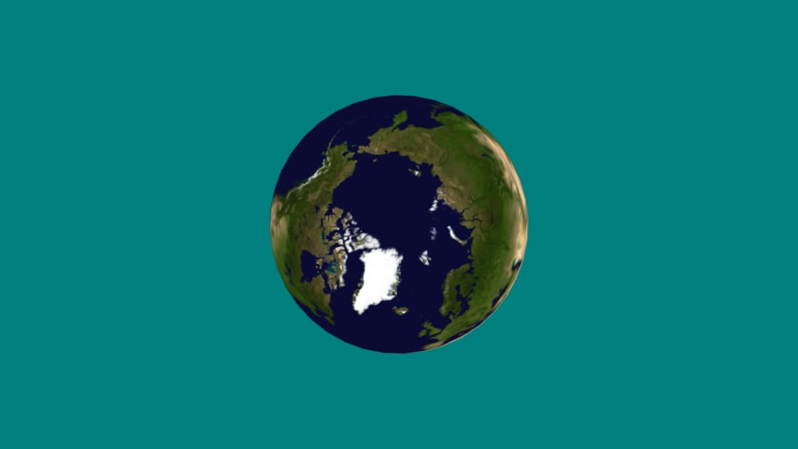
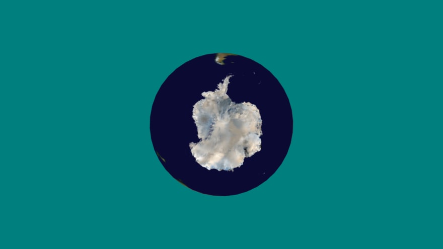
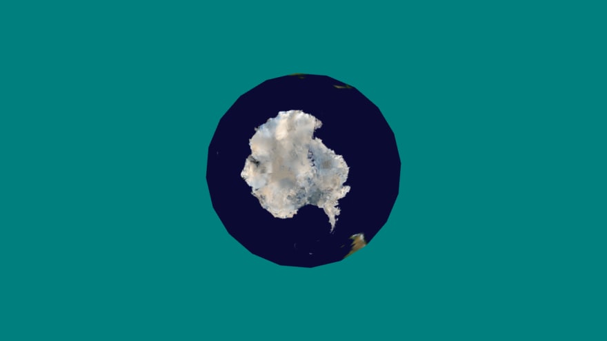
Better. One thing to keep in mind is that at lower poly counts the texture will get more distorted at the poles as the seams will become more visible on the pyramid pieces. The above was at density 20.
Density 10:
Density 5:
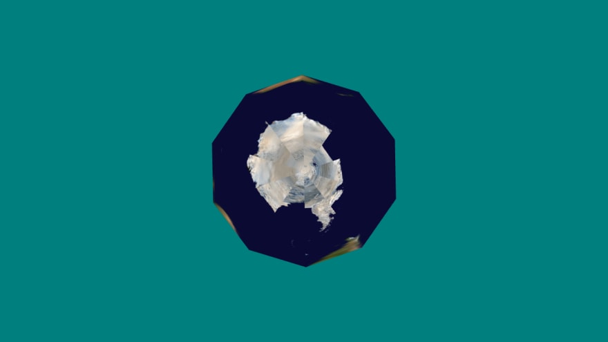
Basically, we'd have to edit the texture if we want to do really low poly (you might envision why, there are triangles at the top and bottom that get bigger with chunkier polys because they fold over more than on a sphere). The equirectangular texture is really designed for real spheres.
We haven't really talked about normals yet (we'll get to them next time) but it makes sense to do this here. A normal is a vector that points "out" from a surface and are used a lot with lighting effects. For a sphere this is easy, it's a normalized ray coming the center of the sphere to the vertex on the surface. Since our sphere is located at the origin it's just the normalized point. In fact since our sphere is always radius 1, it's already normalized. Nice! Just keep in mind if you change those parameters you will need to calculate it. For completion's sake:
normals: positions.flat(),flat is a copy so that's all we need.That was actually a lot harder than I thought but we learned some good stuff about UVs. Next time we'll be able to use this new shape to showcase some new lighting effects.
Full code for this milestone is here but it's a bit jumbled with some stuff I started working on first. It'll make more sense next time.
https://github.com/ndesmic/geogl/tree/v3
https://github.com/ndesmic/geogl/tree/v3
41
